CAD models
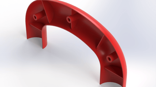
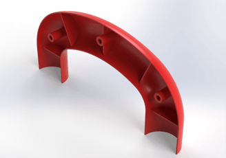
Injection molded handle
This injection molded handle half is designed for use in tools or toolboxes, providing an ergonomic grip for user comfort and durability. Injection molding ensures a strong, lightweight structure with precise tolerances, making it ideal for applications in hand tools, power tools, or storage cases.
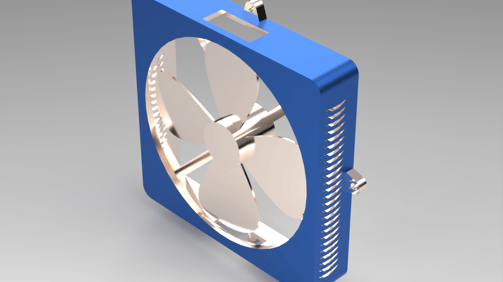
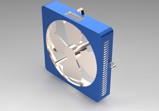
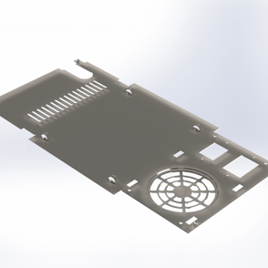
Fan housing assembly
This square fan assembly is designed for cooling and ventilation applications in electronic enclosures, HVAC systems, and industrial equipment. The fan housing and blades, typically made from thin sheet metal or plastic, ensure a lightweight yet durable construction.
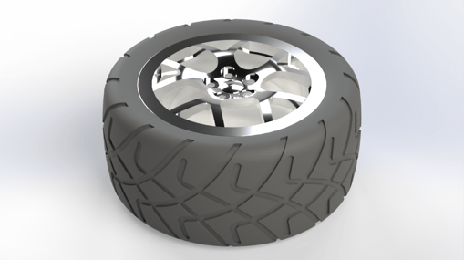
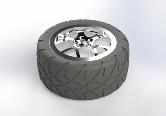
Wheel assembly
This automotive wheel assembly, consisting of the rim, tire, and hubcap, is designed for use in passenger vehicles, providing both functionality and aesthetic appeal. The tire was modeled using a revolved cross-section to accurately represent real world manufacturing techniques like extrusion and molding.
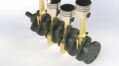
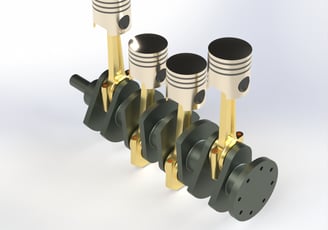
Four-cylinder engine
This inline four-cylinder engine assembly showcases the core components of internal combustion engines, including the crankshaft, pistons, piston rings, connecting rods, and rod caps. Designed to emphasize the breakdown of complex assemblies into manageable parts, this model highlights key engineering principles such as motion mechanics, material strength, and assembly constraints.
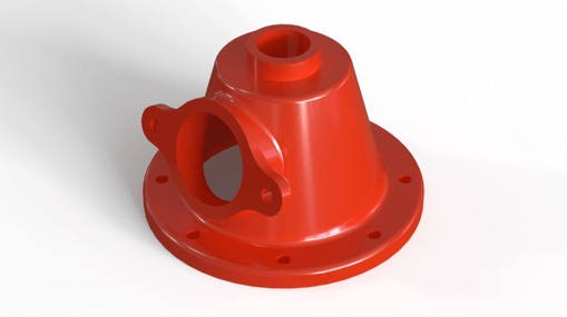
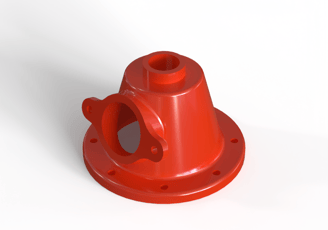
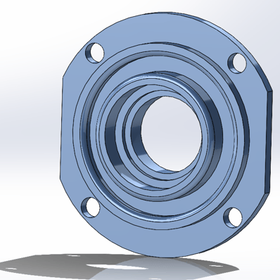
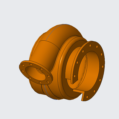
Housing cover
This 5-inch housing cover is designed to protect critical motor or pump components from external elements such as dust, moisture, and debris. Created using a revolved cross section, the design ensures a precise, symmetrical shape ideal for enclosing rotating or sensitive internal parts. Additional features, such as mounting points and ventilation holes, were strategically added to enhance functionality and ease of assembly.
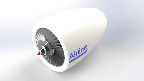
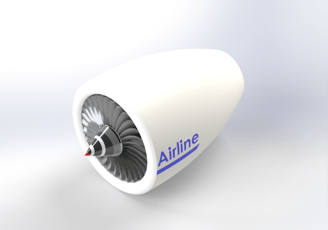
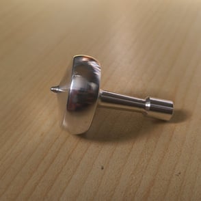
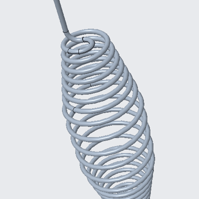
Jet engine assembly
This simplified jet engine assembly consists of three main components: the propeller, shaft, and housing, demonstrating fundamental principles of propulsion and aerodynamics. The propellers were modeled using a spline based cross section and 3D sketching techniques to achieve an aerodynamic blade shape. The shaft and housing were created using a revolved cross section provide a streamlined shape.
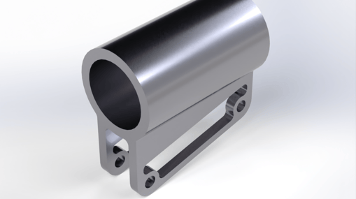
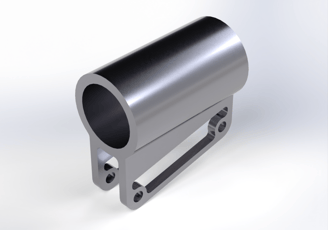
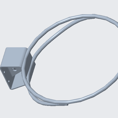
Flag pole bracket
This flag pole bracket is designed to securely mount a flag pole to a surface, ensuring stability and durability in various environmental conditions. The model was created by extruding the side profile of the bracket, followed by cut extrusions to incorporate mounting holes and cutouts for proper fitment. Due to its symmetrical design, the mirror feature was utilized to streamline the modeling process.
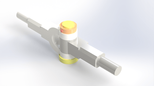
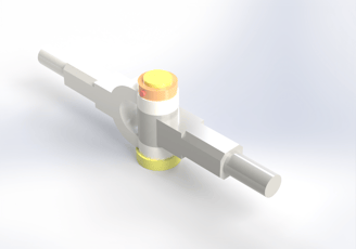
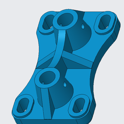
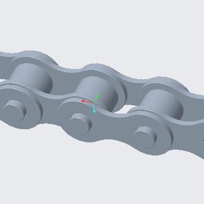
Knuckle joint assembly
This knuckle joint assembly consists of five key components: the fork, eye, collar, bolt, and pin, working together to create a strong and flexible mechanical connection. Designed to handle axial loads while allowing limited angular movement, this assembly is commonly used in applications requiring reliable load transfer, such as tractor linkages and trailer hitch connections in pickup trucks.
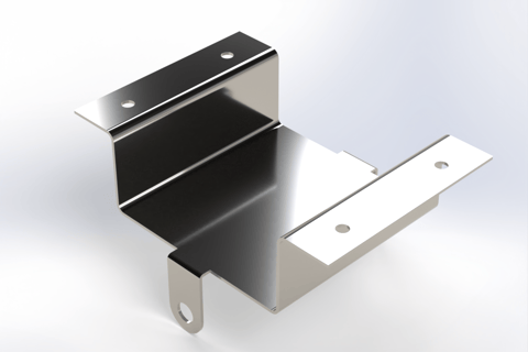
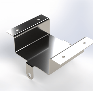
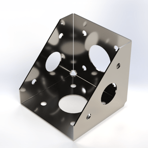
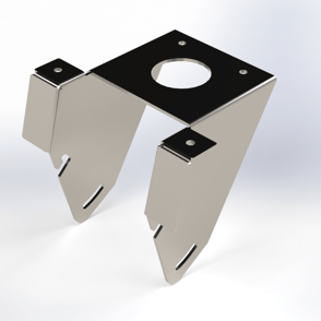
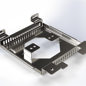
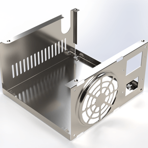
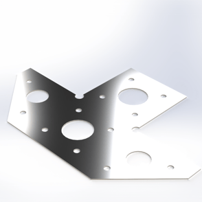
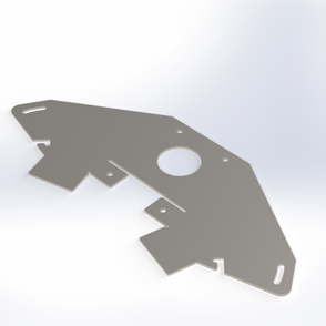
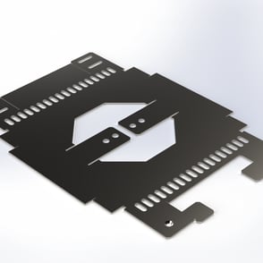
Sheet metal designs
This section showcases four sheet metal bracket designs, each demonstrating efficient use of SolidWorks sheet metal tools. Both flat pattern and fully bent versions are included, highlighting the transition from design to manufacturable parts. These models reflect the versatility of sheet metal practices used in fabricating durable, lightweight components
Creo Parametric
CAM models
Fusion 360 Manufacturing
This section highlights hands on experience gained through coursework in manual and CNC machining, providing a strong foundation in one of the most widely used manufacturing methods. The introductory course focused on traditional machining techniques using Bridgeport Series 1 Knee Mills for standard face and end milling operations, as well as RKL-15XX manual lathes for essential turning processes such as facing, knurling, thread cutting, and parting off. These exercises emphasized precision, tool control, and material considerations, essential skills for any engineer working with machined components.
Building on this foundation, the second part of the course introduced CNC machining, where modern automation and programming techniques were explored using the VF4-CNC Mill and DS-30Y CNC Lathe. Training included machine setup, tool selection, and CAM software programming to execute complex machining operations with high precision. This experience reinforced an understanding of machining principles, part tolerances, and manufacturing workflows, providing valuable insight into the capabilities of CNC technology.
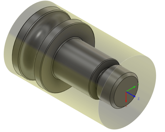
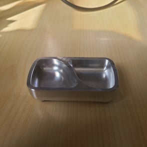
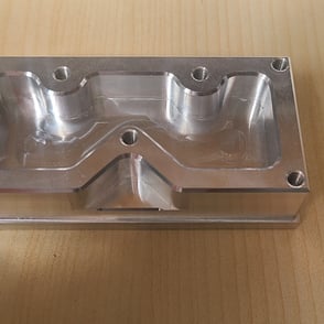
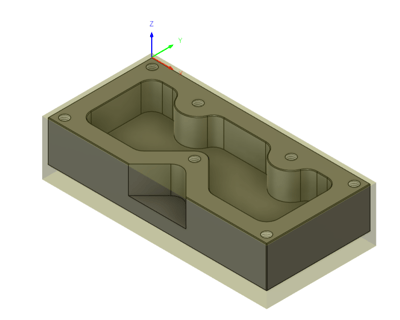
CAM setup
Using Fusion 360's manufacturing tab the first setup for the part was created. This part required two separate operations to achieve the final product
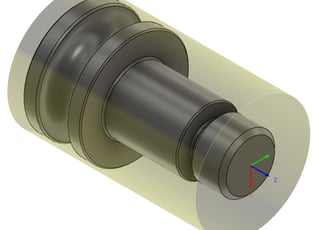
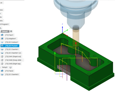
Setup simulation
By closely following the guidelines discussed in class all operations were setup and the simulations were observed closely to
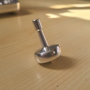
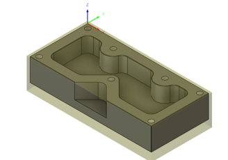
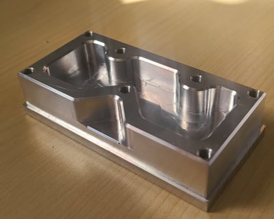
Machined part
After the CAM setup was verified for accuracy an appropriate piece of aluminum stock was setup in the VF4-CNC vice where both operations were completed
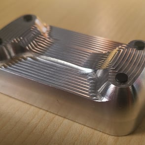
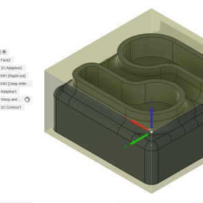
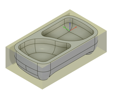
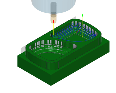
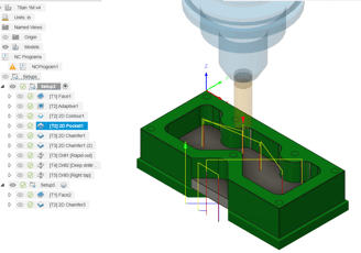
CAM setup
Using Fusion 360's manufacturing tab both setups were created. This includes the facing, adaptive, and contour operations
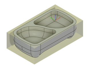
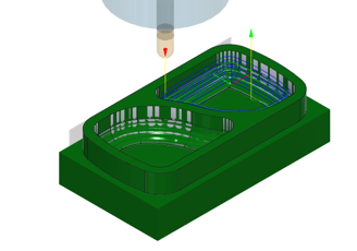
Setup simulation
All the setups created were closely observed in the simulations before proceeding to cutting the stock
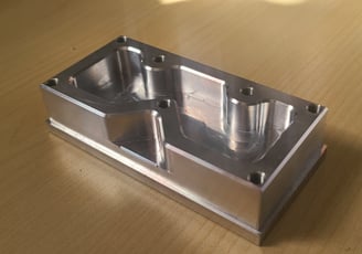
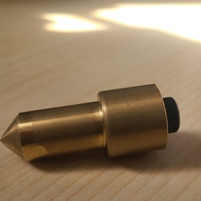
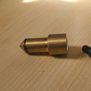
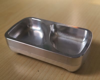
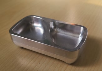
Machined part
After the CAM setup was verified for accuracy an appropriate piece of aluminum stock was setup in the VF4-CNC vice where both operations were completed